
Hydraulic Concrete Placing Boom
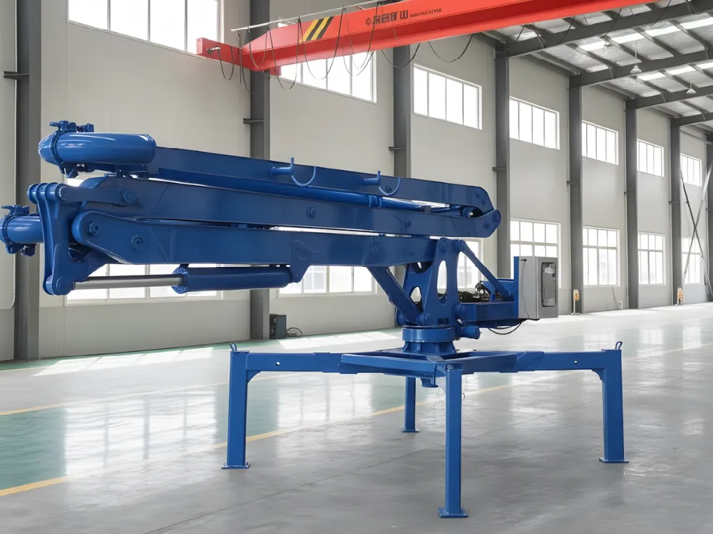
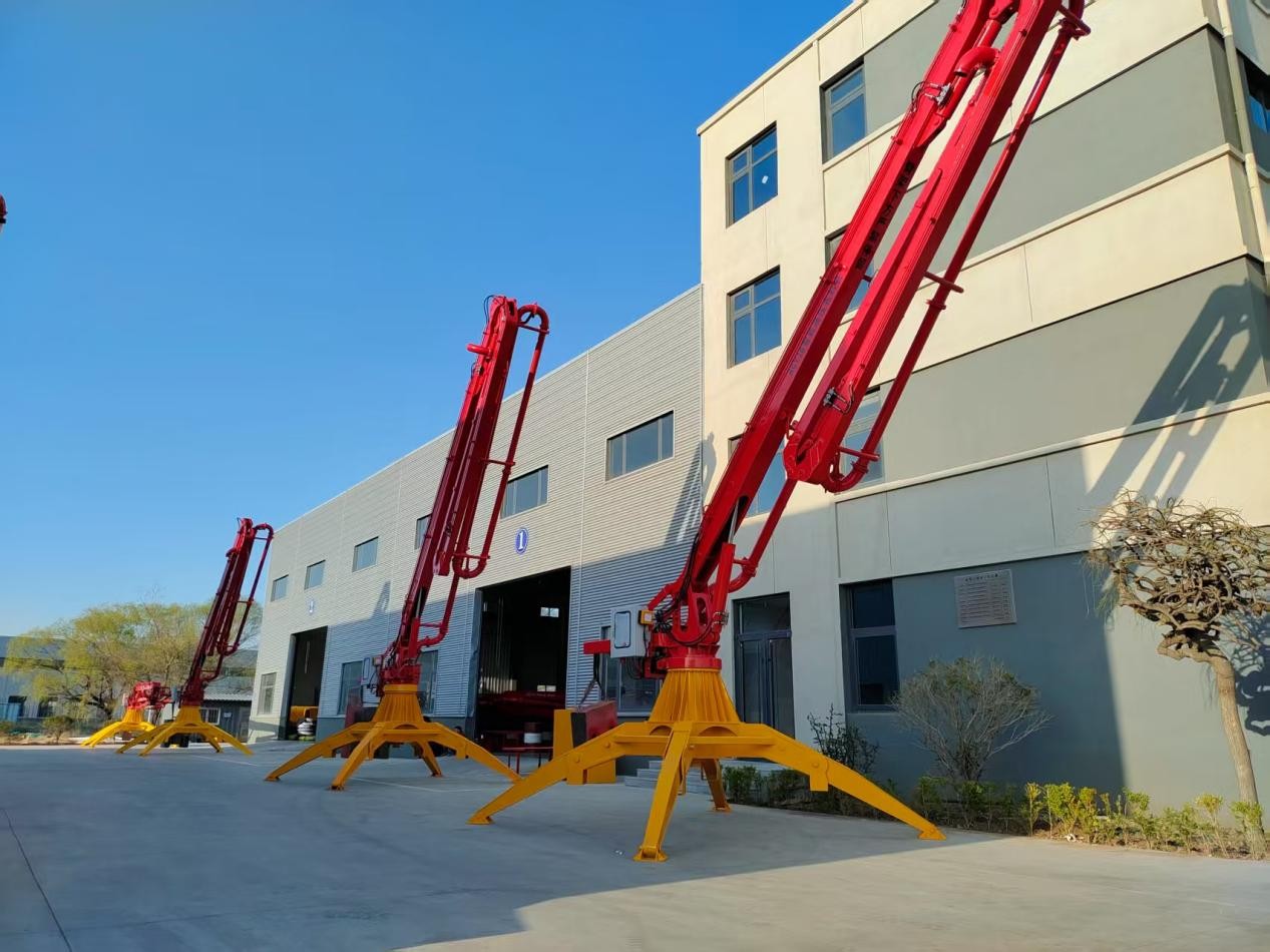
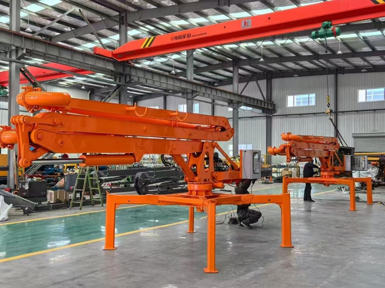
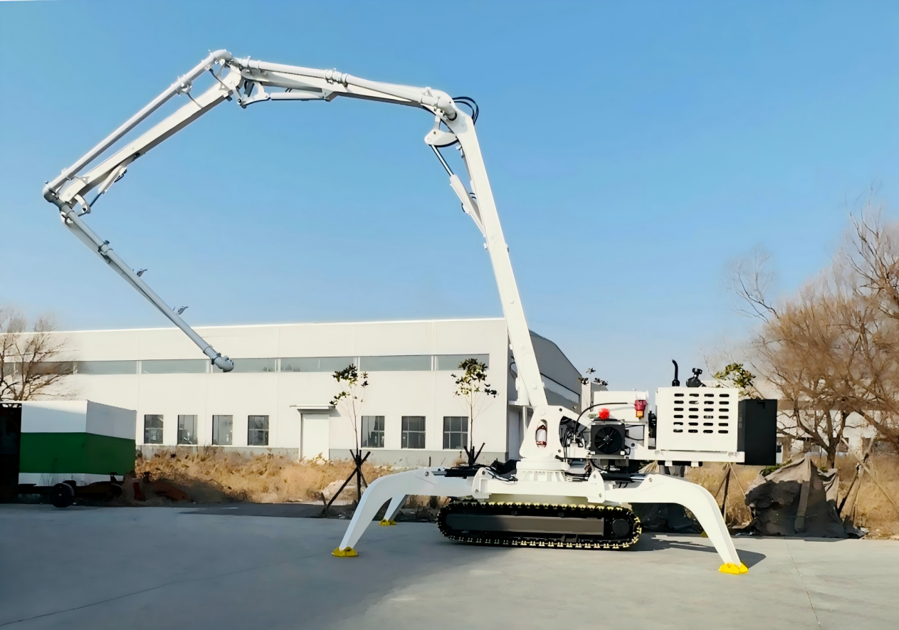
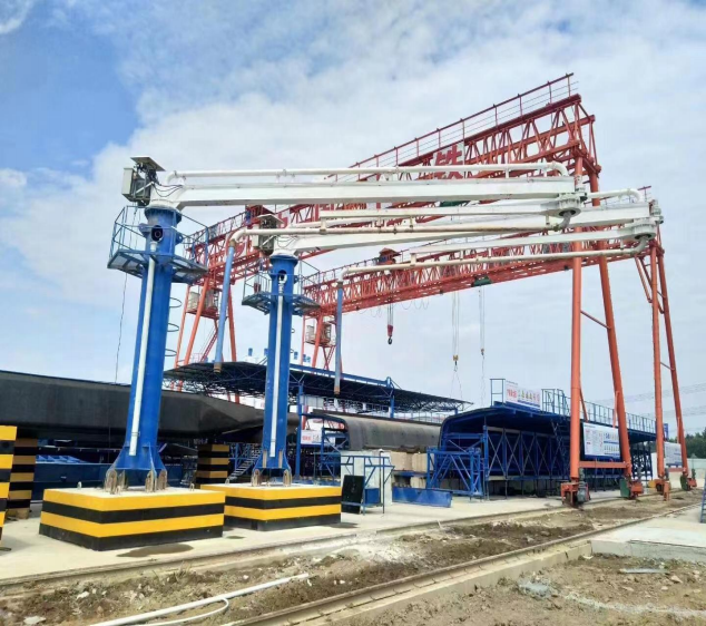
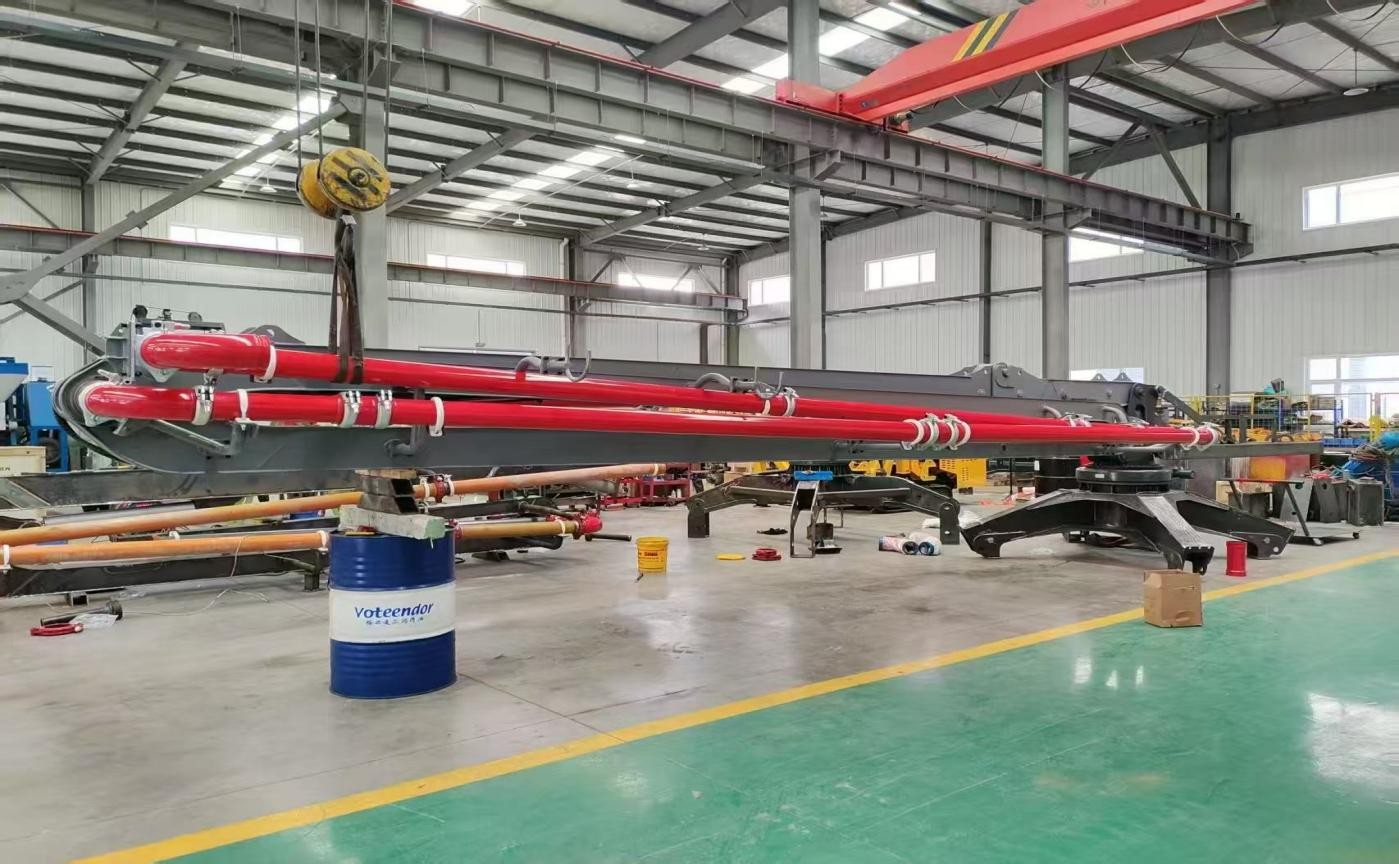
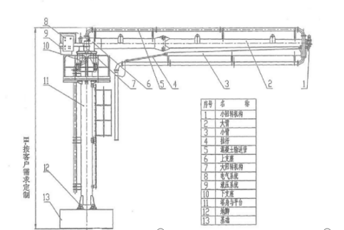
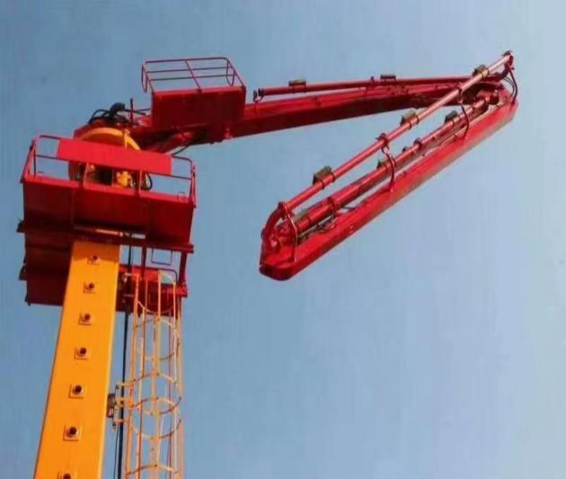
A Hydraulic Concrete Placing Boom, often integrated with a concrete pump to form a complete pumping system, is a mechanized arm used for precise concrete placement. It consists of multiple articulated boom sections, a rotating base, and a delivery pipeline. Powered by a hydraulic system, it can rota
Product Details
Product Overview
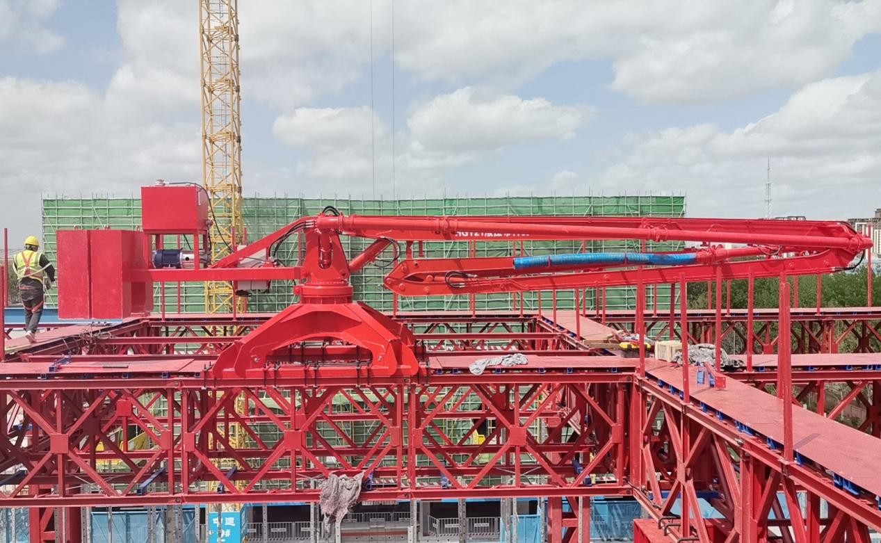
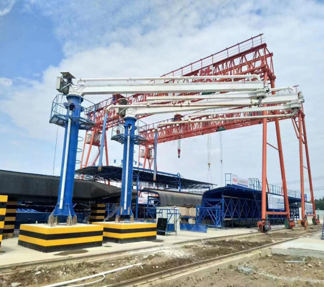
The hydraulic concrete placing boom is a mechanized distributing arm mounted on floor slabs, platforms or simple supports. Connected to a concrete pump, it delivers fresh concrete through a pipeline to any point within its working radius, eliminating manual hose handling and re-piping on every pour. Models HGY12-2 to HGY23-3R cover horizontal reaches from 11.6 to 22.5 m with 360° continuous slewing and boom elevation angles from 0° to 90°, suiting mid-rise to super high-rise construction.
Compared with fixed pipelines, the placing boom cuts labor cost, accelerates pour cycles and keeps the concrete pump stationary, which is why it has become standard equipment on tower cranes, elevator-shaft cores and large floor plates.
Working Principle
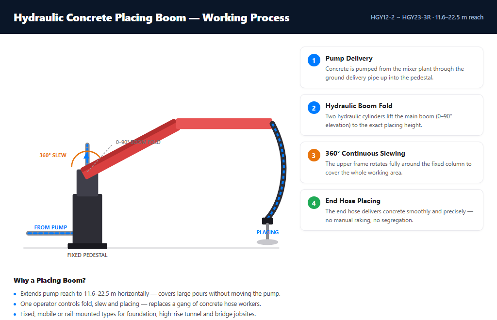
The boom is a hydraulically actuated articulated arm with a concrete pipeline running along its full length. Concrete is pumped continuously from the trailer or truck-mounted pump into the pipeline inlet, flows through the pipe to the end hose, and is discharged exactly at the pour point. The operator controls boom extension, folding, slewing and elevation through a remote control unit, so one person can position concrete over a large area without moving the pump or re-routing pipes. A normally-closed slewing brake and overload protection devices keep the boom locked and stable whenever the hydraulic system is inactive.
Boom Structure & Arm Configurations
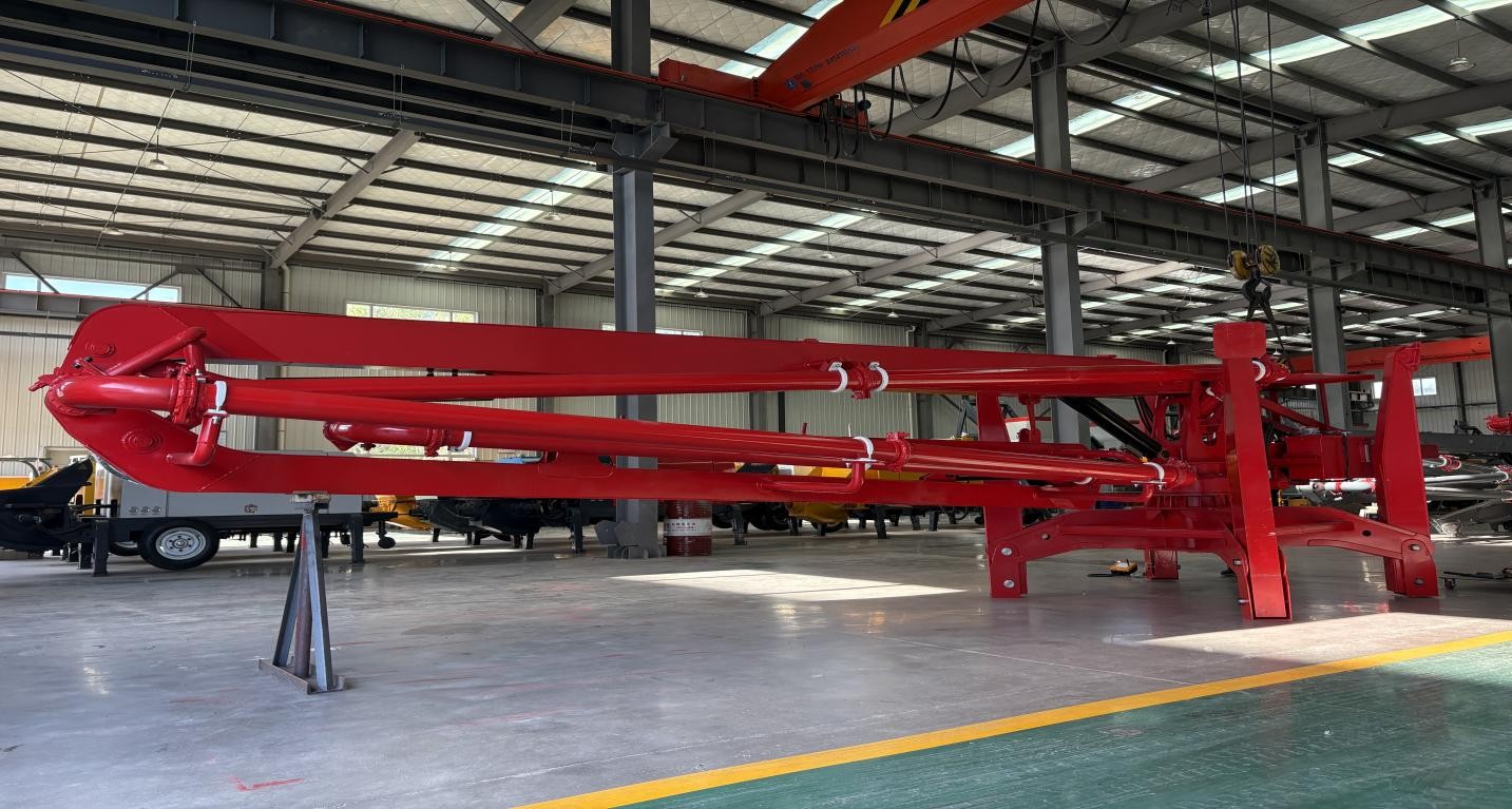
R-type arm – compact folded profile, ideal for narrow elevator shafts and congested job sites.
RZ-type arm – combines R and Z folding to reduce unfolded height while keeping long horizontal reach; best for standard floor-to-floor pours.
M-type arm – maximum unfolding in a balanced layout, preferred for large floor plates and high-rise cores.
All configurations rotate 360° continuously and can extend, fold and luff simultaneously, allowing the operator to cover the full pour area without repositioning the boom.
Key Features
360° continuous slewing – hydraulic slewing mechanism with normally-closed brake, smooth and lockable at any angle.
Independent hydraulic system – self-contained power unit, no connection to the pump's hydraulics required.
Remote control operation – one operator positions the boom precisely from the pour point, improving safety and pour accuracy.
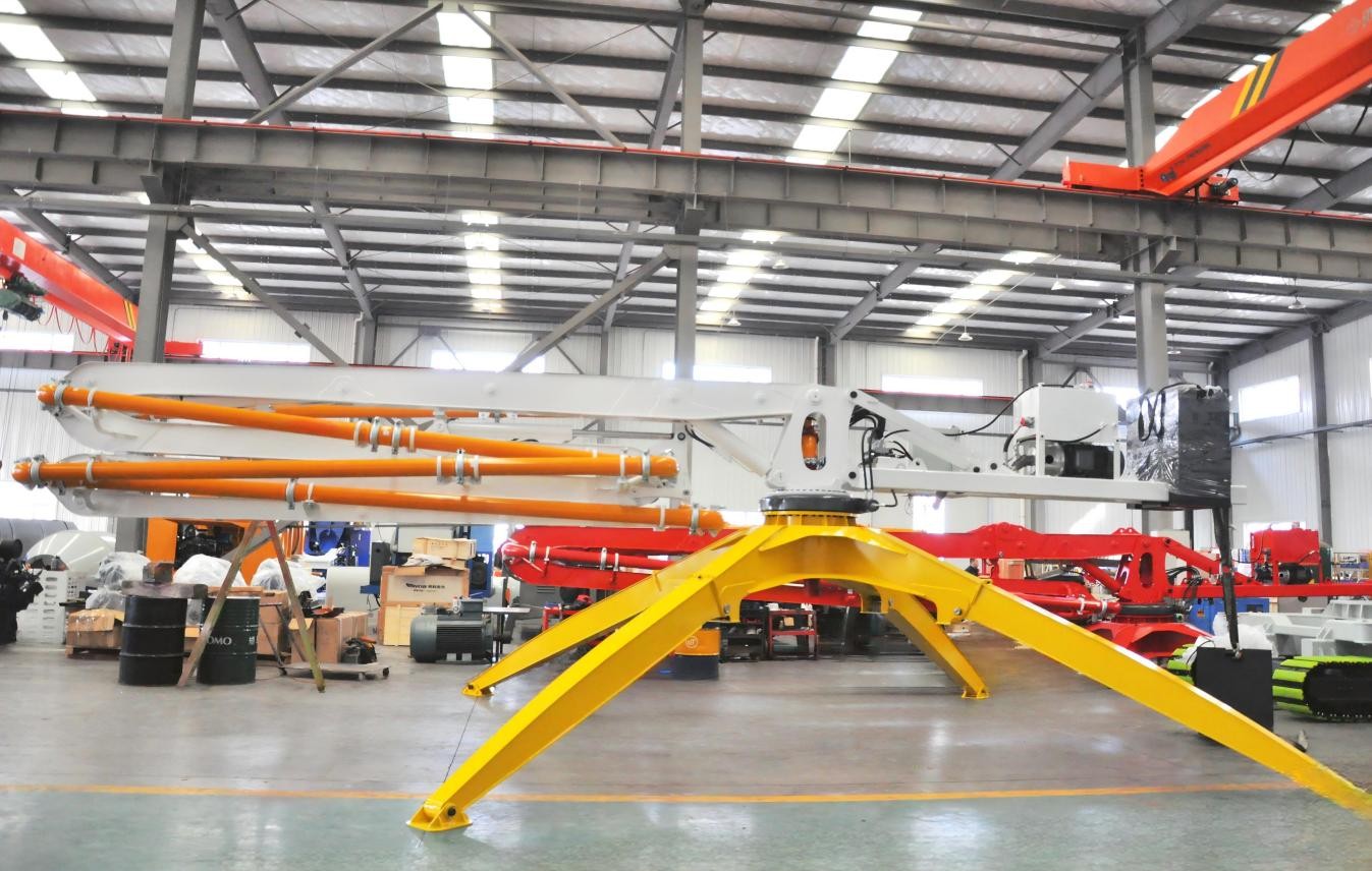
High adaptability – no fixing or anchoring needed; the boom can be crane-lifted onto floor slabs, platform frames or simple supports and moved with the work face.
Compact transport – fully folded dimensions allow transport by standard truck and hoisting by tower crane or mobile crane.
Safety protection – overload alarm, anti-tipping interlock and emergency stop as standard on every model.
Applications
High-rise and super high-rise buildings – elevator-shaft core and floor plate concrete placing.
Bridges and viaducts – deck and pier pours over long horizontal distances.
Dams, locks and hydraulic structures – large-volume continuous pours with limited access.
Mass concrete foundations – rapid, even spreading over large raft slabs.
How to Select the Right Placing Boom
Choose the model by three figures: your required horizontal reach (m), the available mounting height, and the pour point layout. For floors up to 12 m reach, HGY12-2 is the economy choice; for 15–17 m standard floors, HGY15-3 or HGY17-3; for high-rise cores and large plates up to 22.5 m, HGY21-3R, HGY21-4M or HGY23-3R. Tell us your building height, floor plan and pump delivery rate – we will recommend the model, mounting method and pipeline layout, and provide an installation drawing.
Product Specifications
Concrete Placing Boom — Model Comparison
Table 1 — Standard Placing Booms
| Parameter | HGY12-2 | HGY14-3Z | HGY15-3 | HGY17-3 | HGY21-3R | HGY21-4M | HGY23-3R |
|---|---|---|---|---|---|---|---|
| Model | HGY12-2 | HGY14-3Z | HGY15-3 | HGY17-3 | HGY21-3R | HGY21-4M | HGY23-3R |
| Horizontal reach (m) | 11.6 | 13.5 | 15 | 16.5 | 20.6 | 20.5 | 22.5 |
| Rotation (°) | 360 | 360 | 360 | 360 | 360 | 360 | 360 |
| Elevation angle (°) | 0–87 | 0–80 | 0–90 | 0–90 | 0–80 | 0–84 | 0–80 |
| Slewing brake | Normally closed | Normally closed | Normally closed | Normally closed | Normally closed | Normally closed | Normally closed |
| Max allowable working wind speed | — | Force 6 | — | — | Force 6 | — | Force 6 |
| Working environment temperature | -5–40℃ | -5–40℃ | -5–40℃ | -5–40℃ | -5–40℃ | -5–40℃ | -5–40℃ |
| Weight without counterweight (T) | 1.9 | 2.1 | 3.23 | 2.7 | 4.0 | 7.7 | 4.5 |
| Weight with counterweight (T) | 2.9 | 3.5 | 5.43 | 4.9 | 6 | 9.9 | 6.5 |
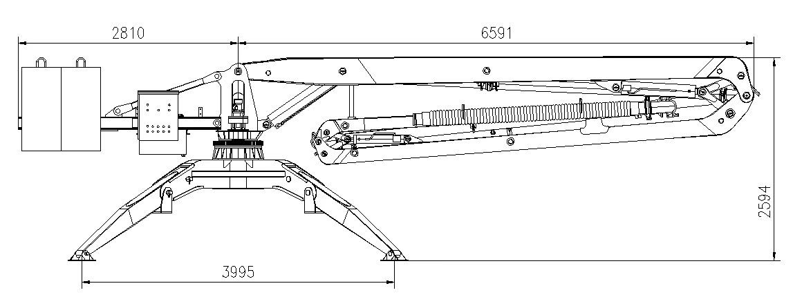
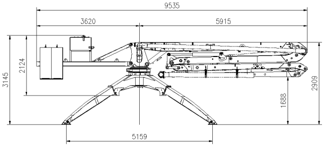
| Outrigger span (mm) | 2325×2325 | — | 4000×4000 | 4000×4000 | — | 5160×5160 | — |
| Overall dimensions L×W×H (mm) | — | 6294×1865×1920 | — | — | — | — | — |
| Power supply | 380V/50Hz | 3-phase 380V | 380V/50Hz | 380V/50Hz | 380V/50Hz | 380V/50Hz | 380V/50Hz |
| Output power (kW) | 4 | 4 | 4 | 4 | 5.5 | 22 | 5.5 |
| Protection grade | IP54 | — | IP54 | IP54 | IP54 | IP54 | IP54 |
| Insulation class | F | — | F | F | F | F | F |
| System pressure (MPa) | 20 | 20 | 20 | 20 | 30 | 32 | 30 |
| Control mode | Panel / Radio remote | Switching remote | Cable / Radio remote | Cable / Radio remote | Switching remote | Analog remote | Switching remote |
| Boom folding type | 2-section R | 3-section R | 3-section R | 3-section R | 3-section R | 4-section M | 3-section R |
| Multi-way valve | — | Switching | — | — | Switching | Proportional | Switching |
| Delivery pipe inner diameter (mm) | Φ125 | Φ125 | Φ125 | Φ125 | Φ125 | Φ125 | Φ125 |
| End rubber hose (m) | 3 | 3 | 3 | 3 | 3 | 3 | 3 |
| Section length (mm) | 6300 / 5306 | — | 6000 / 5000 / 4000 | 6500 / 5500 / 4500 | — | 6498 / 4600 / 4600 / 5312 | 8000 / 7350 / 7250 |
| Section folding angle (°) | 87 / 195 | 80 / 180 / 195 | 90 / 180 / 180 | 90 / 180 / 180 | 80 / 180 / 195 | 90 / 180 / 235 / 180 | 75 / 180 / 195 |
| Rubber hose / electrical brand | — | Manuli / Schneider | — | — | — | — | — |
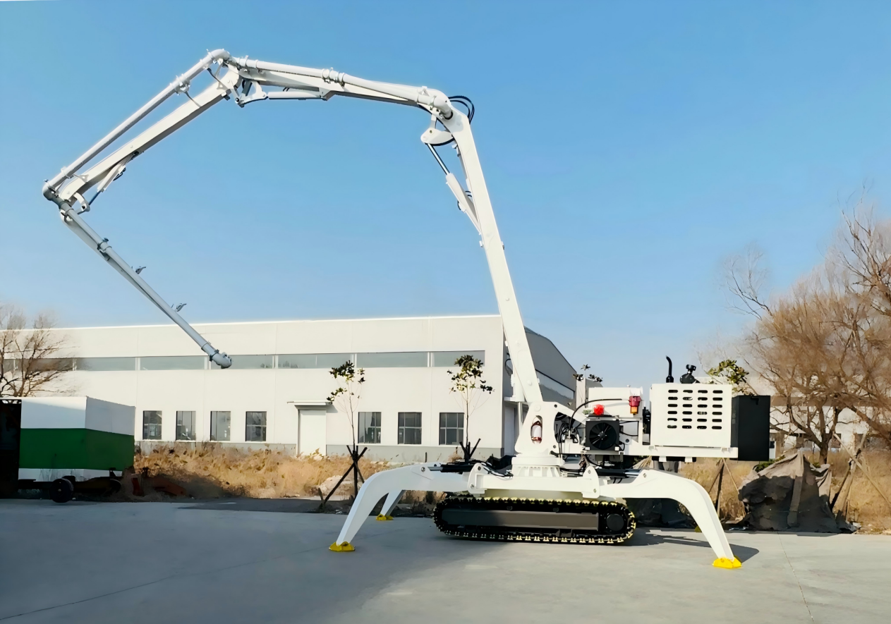
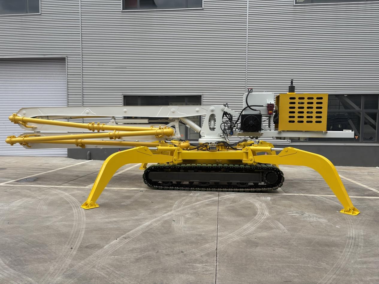
Table 2 — Crawler Placing Booms
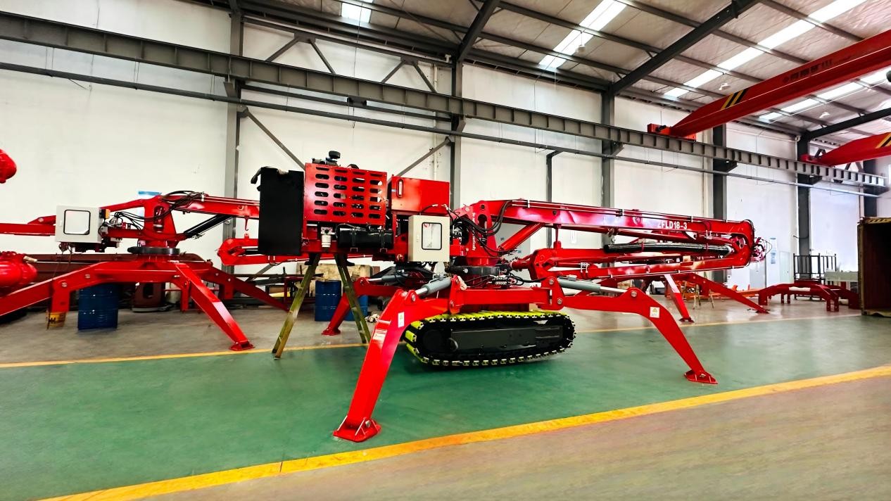
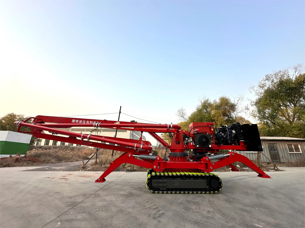
| Parameter | HGL19-2 | HGL20-4 | HGY23-4 |
|---|---|---|---|
| Model | HGL19-2 | HGL20-4 | HGY23-4 |
| Placing height (m) | 19 | 19.8 | 22.5 |
| Placing radius (m) | 16.5 | 19.8 | 20.15 |
| Rotation (°) | 360 | 360 | 360 |
| Elevation angle (°) | 0–90 | 0–90 | 0–90 |
| Slewing brake | Normally closed | Normally closed | Normally closed |
| Working environment temperature | -5–40℃ | -5–40℃ | -5–40℃ |
| Total weight (T) | 5.8 | 8.5 | 8.8 |
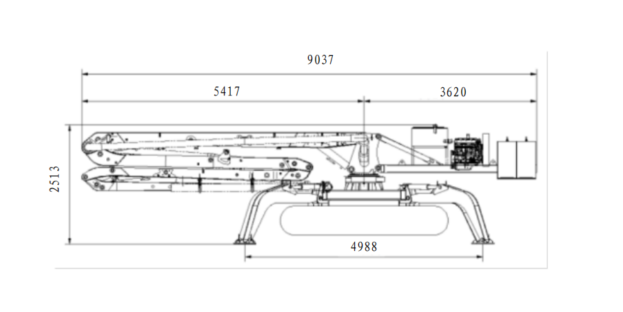
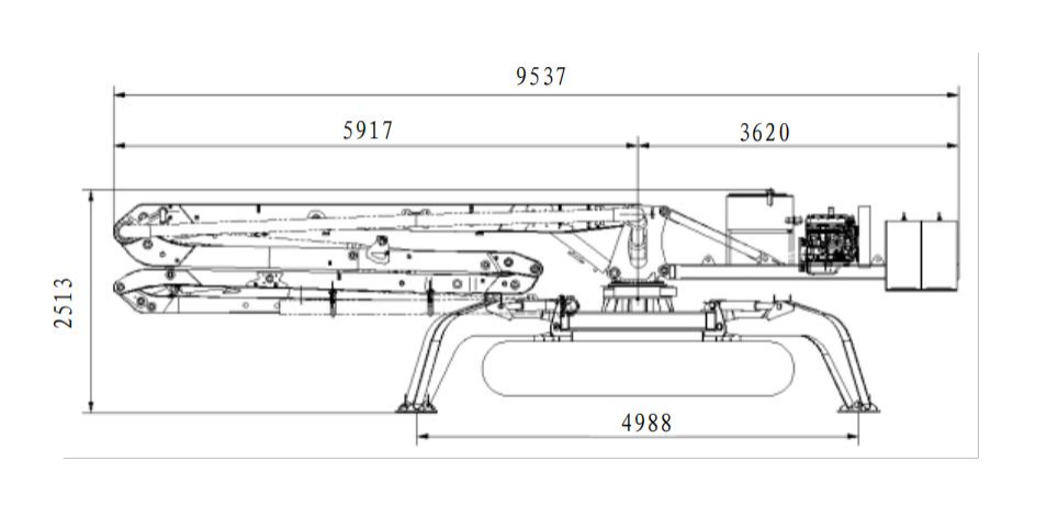
| Outrigger span (mm) | — | 4988×4988 | 4988×4988 |
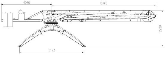
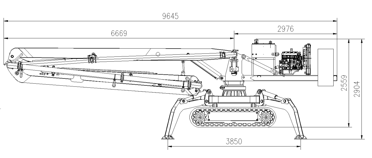
| Transport dimensions (mm) | 9479×2100×2510 | — | — |
| Overall dimensions — non-working (mm) | — | 9037×2200×2513 | 9537×2200×2513 |
| Power source | Diesel engine | Diesel engine | Diesel engine |
| Power (kW) | 55 | 65 | 65 |
| Engine brand | Yunnei Power | Yunnei Power | Yunnei Power |
| System pressure (MPa) | 20 | 32 | 32 |
| Control mode | Cable / Radio remote | Manual / Radio remote (analog) | Manual / Radio remote (analog) |
| Boom folding type | 3-section R | 4-section M | 4-section M |
| Delivery pipe inner diameter (mm) | Φ125 | Φ125 | Φ125 |
| End rubber hose (m) | 3 | 3 | 3 |
| Section length (mm) | 6500 / 5500 / 4500 | 5150 / 4000 / 4050 / 4450 | 5775 / 4625 / 4675 / 5075 |
| Section folding angle (°) | 90 / 180 / 180 | 90 / 180 / 230 / 195 | 90 / 180 / 230 / 195 |
| Crawler dimensions (mm) | 2450×1700×500 | 3500×2100×600 | 3500×2100×600 |
| Track width (mm) | 400 | — | — |
| Max traveling speed (km/h) | 3 | 3 | 3 |
| Travel engine | — | Yunnei 65kW | Yunnei 65kW |
Table 3 — Horizontal Placing Boom
| Parameter | HGY19-2 |
|---|---|
| Model | HGY19-2 |
| Max working radius (mm) | 19000 |
| Main boom slewing range | ±360° |
| Jib slewing range | 360° free rotation |
| Hydraulic system motor power (kW) | 4 |
| Main slewing speed (r/min) | 0.2–0.3 |
| Jib slewing speed (r/min) | 0.2–0.3 |
| Concrete delivery pipe spec | Φ125 |
| End hose length (mm) | 3000 |
| Total weight (T) | 5.3 (excl. concrete base) |
Table 4 — Internal-Climbing Placing Booms
| Parameter | HGY21-3 | HGY24/3 (shaft) | HGY24/3 (floor) | HGY28 | HGY32/3 | HGY33/4 | HGY36/4 |
|---|---|---|---|---|---|---|---|
| Model | HGY21-3 | HGY24/3 | HGY24/3 | HGY28 | HGY32/3 | HGY33/4 | HGY36/4 |
| Placing radius (m) | 21 | 24 | 24 | 28 | 32 | 32.7 | 36 |
| Working height (m) | — | 22.5 | 22.5 | 22.5 | 22.5 | 22.5 | 22.5 |
| Section length (m) | — | — | 8.5 / 7.5 / 6.5 | 10.5 / 9.2 / 8 | 13.85 / 10.6 / 7.56 | 8.86 / 7.96 / 7.96 / 7.96 | 11.4 / 8 / 8 / 8 |
| Boom folding angle (°) | — | 0–90 / 0–180 / 0–180 | 0–90 / 0–180 / 0–180 | 0–90 / 0–180 / 0–180 | 0–90 / 0–180 / 0–180 | -2–85 / 0–180 / 0–180 / 0–180 | 0–90 / 0–180 / 0–180 / 0–180 |
| Slewing range | — | 360° | 360° | 360° | 360° | 360° | 360° |
| Rotation (°) | 360 | — | — | — | — | — | — |
| Swiveling speed (r/min) | 0.32 | 0–0.25 | 0–0.25 | 0–0.25 | 0–0.25 | 0–0.25 | 0–0.25 |
| Slewing brake | Normally closed | — | — | — | — | — | — |
| Elevation angle (°) | 0–85 | — | — | — | — | — | — |
| Working environment temperature | -5–40℃ | — | — | — | — | — | — |
| Weight (T) | 11.7 | — | — | — | — | — | — |
| Motor power (kW) | — | 18.5 | 18.5 | 18.5 | 18.5 | 30 | 30 |
| Output power (kW) | 5.5 | — | — | — | — | — | — |
| System pressure (MPa) | 32 | 32 | 32 | 32 | 32 | 32 | 32 |
| Hydraulic oil grade | — | Winter H46 / Summer H68 | Winter H46 / Summer H68 | Winter H46 / Summer H68 | Winter H46 / Summer H68 | Winter H46 / Summer H68 | Winter H46 / Summer H68 |
| Protection grade | IP54 | — | — | — | — | — | — |
| Insulation class | F | — | — | — | — | — | — |
| Climbing method | — | Elevator shaft | Floor climbing | Floor climbing | Floor climbing | Floor climbing | Floor climbing |
| Free-standing height (m) | — | Standard section | 22.5 | 22.5 | 22.5 | 22.7 | 22.5 |
| Operation mode | — | Cable / Radio / Panel remote | Cable / Radio / Panel remote | Cable / Radio / Panel remote | Cable / Radio / Panel remote | Cable / Radio remote | Cable / Radio / Panel remote |
| Control mode | Radio remote | — | — | — | — | — | — |
| Power supply | 380V/50Hz | 380V/50Hz | 380V/50Hz | 380V/50Hz | 380V/50Hz | 380V/50Hz | 380V/50Hz |
| Wind speed — working (km/h) | — | ≤56 | ≤56 | ≤56 | ≤56 | ≤60 | ≤56 |
| Wind speed — non-working (km/h) | — | ≤72 | ≤72 | ≤72 | ≤72 | ≤28 | ≤72 |
| Working temperature | — | -20–40℃ | -20–40℃ | -20–40℃ | -20–40℃ | 0–40℃ | -20–40℃ |
| Working altitude (m) | — | ≤1000 | ≤1000 | ≤1000 | ≤1000 | — | ≤1000 |
| Self-weight (kg) | — | 22000 | 22000 | 22000 | 22000 | 21800 | 24000 |
| Delivery pipe inner diameter (mm) | Φ125 | Φ125 | Φ125 | Φ125 | Φ125 | Φ125 | Φ125 |
| End rubber hose (m) | 3 | — | — | — | — | — | — |
| Boom folding type | 2-section | — | — | — | — | — | — |
| Fixed arm (mm) | 2516 | — | — | — | — | — | — |
| Climbing height (m) | 0–4 (adjustable) | — | — | — | — | — | — |
| Climbing speed (m/min) | 0.6 | — | — | — | — | — | — |
| Tower structure (mm) | Truss 1000×1000 | — | — | — | — | — | — |
NOTE: Capacity figures are based on general throughput of medium hardness materials. Actual performance may vary depending on feeding size, rock types and water content.
Installation & Service Process
Foundation Drawing
Within 3 days after signing
Professional engineers provide customized foundation drawings based on your site conditions.
Installation & Commissioning
10-15 days
Two experienced engineers provide on-site installation guidance and equipment commissioning.
Operator Training
2-3 days
Comprehensive training covering both theory and hands-on practice for your team.
After-Sales Support
24/7 Technical Support
- Video diagnosis within 2 hours
- Spare parts dispatched within 48 hours
- On-site engineer within 7 days (major countries)
Frequently Asked Questions
How far can a concrete pumping machine deliver concrete?
What projects is a concrete trailer pump suitable for?
What are the advantages of a trailer mounted concrete pump?
What is a multifunctional concrete trailer pump?
Related Products
Get a Quotation
Please fill in the form below (* are required) to send us a brief message, we will reply to you within 12 hours/provide you with the latest quotes.
SERVICE PROMISE
Senior technical engineers provide you with customized solutions and professional installation services to effectively solve your problem in after-sales.